Leave Your Message

What Are Heating Cables and How Do They Work?

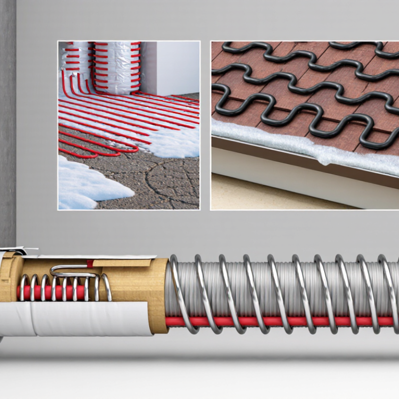
Heating Cables are flexible electrical systems designed to produce controlled heat along pipes, roofs, floors, tanks, and outdoor surfaces. They prevent freezing, maintain process temperatures, and improve comfort in cold environments. Yet their operation is often misunderstood. A cable does not “create warmth” magically. It converts electrical energy into measured heat through a resistive conductor.

John Siegenthaler, P.E., a respected heating engineer and educator, explains the design principle clearly: “Good heat tracing is designed around heat loss, not guesswork.” That idea matters. A cable installed on an exposed water pipe faces different demands from one placed beneath a tiled floor. Insulation, cable spacing, moisture, surface material, and local temperature all affect performance. Small details matter.

Inside most Heating Cables, electrical resistance generates heat when current passes through the conductor. Some cables deliver constant wattage. Others regulate their output as surrounding temperatures change. Self-regulating types can reduce energy use and lower overheating risks, although they are not automatically safe in every installation. They still require correct sizing, grounding, controls, and inspection.

This guide examines how Heating Cables work, where they are used, and what separates reliable installation from a temporary fix. The subject seems simple. It is not always. Real buildings lose heat unevenly, and installation mistakes can remain hidden until winter arrives. Manufacturer instructions and qualified electrical advice should therefore guide every project. Even experienced installers can overlook one weak point. That is worth remembering.
What Are Heating Cables and How Do They Work?

Defining Heating Cables: Resistive Conductors, Insulation, and 5–40 W/m

Heating cables are electrical conductors designed to turn controlled current into heat. Their core uses a resistive metal alloy. As electrons meet resistance, electrical energy becomes thermal energy along the cable. A 5 W/m cable releases five watts for each metre under stated operating conditions. Higher ratings, up to 40 W/m, provide stronger heating but demand better heat dissipation and control. Simple principle. Uneven heat can still cause trouble.

Insulation surrounds the conductor and keeps current contained. It also protects the cable from moisture, abrasion, chemicals, and temperature changes. Common constructions use polymeric, silicone, or fluoropolymer insulation, selected for the installation environment. An outer jacket may add mechanical protection. In field work, installers check bending limits, surface contact, and electrical resistance before energizing. These details matter more than appearance.

Wattage is not a universal promise. Actual output can vary with supply voltage, spacing, ambient temperature, insulation, and thermostat settings. A 20 W/m cable may overheat a poorly ventilated surface, while a 5 W/m cable may underperform outdoors. Ratings must be read with test conditions. It is easy to choose by number alone. That shortcut deserves reconsideration. Professional sizing uses heat-loss calculations, approved installation instructions, and protective electrical devices. Measurements should be documented, not guessed.
What Are Heating Cables and How Do They Work?

Heating cables use resistive conductors to convert electrical energy into heat. Insulation surrounds the conductor to provide electrical isolation, protect against moisture, and help control operating temperature. Typical linear heat outputs range from approximately 5 to 40 W/m.

How to read the chart: A higher watt-per-metre rating produces more heat along the same cable length. For example, a 20 W/m cable releases about 20 watts of heat for every metre when operating at its rated conditions.

How Joule Heating Converts Electrical Power into Controlled Heat

What Are Heating Cables and How Do They Work?

Heating cables use electrical resistance to produce controlled heat. When current passes through a resistive conductor, electrons collide with the material’s structure. These collisions convert electrical energy into thermal energy. This process is called Joule heating. The heat output follows formulas such as P = I²R and P = V²/R. In practical terms, higher current or resistance usually creates more heat. A cable beneath a frozen pipe can raise the pipe’s surface temperature gradually. A thermostat or temperature sensor then switches power on and off, preventing unnecessary heating.

Cable performance depends on spacing, insulation, airflow, and the surrounding surface. Uneven spacing may create hot spots. Poor insulation can waste energy outdoors. I have seen small installation details affect temperature control more than expected. Sensor placement also matters. A sensor mounted too close to the cable may report a false high temperature. Some heating cables adjust their output as conditions change, but they are not magically perfect. Careful testing remains necessary.

Tips: Match the cable’s wattage to the application. Follow the installation instructions and local electrical requirements. Check the cable for damage before energizing it. Keep the sensor firmly attached to the surface being protected. Leave room for inspection, because hidden problems are harder to diagnose.

Self-Regulating vs Constant-Wattage Cables: 5–40 W/m Output Ranges

What Are Heating Cables and How Do They Work?

Self-Regulating vs Constant-Wattage Cables: 5–40 W/m Output Ranges

Heating cables prevent freezing and maintain process temperatures by converting electrical energy into controlled heat. In practice, a 5–40 W/m range covers many applications, from light frost protection to heavily insulated pipework. Constant-wattage cables deliver nearly the same output along their length. A 20 W/m cable remains close to 20 W/m when installed correctly, so spacing and thermostat control matter greatly.

Self-regulating cables respond to surrounding temperature. Their conductive core releases more heat in colder areas and less heat in warmer areas. They can reduce overheating risks, but their output is not perfectly uniform. The cable still needs correct sizing, insulation, and circuit protection. The 2024 ASHRAE Handbook stresses that heat-loss calculations and installation conditions should guide heat-tracing design. The IEA’s Energy Efficiency 2023 report also identifies buildings as responsible for about 30% of global final energy use, making unnecessary electrical heat worth challenging.

Tips: Measure pipe diameter, insulation thickness, minimum temperature, and exposed length before selecting 5, 10, 20, or 40 W/m output. Do not assume higher wattage is always better. Check actual surface temperature during commissioning. A small field error can waste energy for years. IEC 62395 provides useful guidance for electrical heat-tracing systems, but local requirements still deserve careful review.

Selecting Voltage, Watt Density, and Temperature Ratings for Applications

What Are Heating Cables and How Do They Work?

Selecting a heating cable starts with the available voltage. A cable must match the site’s electrical supply and control equipment. Using the wrong voltage can cause weak heating, overheating, or early failure. That choice matters. Heating cables convert electrical energy into controlled heat along pipes, floors, tanks, or equipment. Constant-wattage cables provide steady output, while self-regulating cables adjust heat as surrounding temperatures change.

Watt density describes the heat produced over a specific length or surface area. It is commonly listed in watts per metre or watts per foot. Choose a density that matches the material, insulation, exposure, and required temperature. A pipe outdoors may need more heat than one inside a protected room. However, higher watt density is not automatically better. Excessive output can damage coatings, waste energy, or create uneven temperatures. Practical installation reviews often reveal this mistake.

Temperature ratings require careful attention. Check the cable’s maximum exposure temperature, operating temperature, and the temperature of nearby materials. These values are not interchangeable. Include a suitable sensor and controller when temperature must remain stable. Also confirm bending limits, insulation compatibility, moisture protection, and circuit capacity. Real installations are rarely perfect. Gaps in insulation, sharp bends, and poor contact can change performance significantly. A clean design on paper may still need adjustment after site conditions are measured. Always verify calculations against technical documentation and local electrical requirements before installation.

What Are Heating Cables and How Do They Work? - Selecting Voltage, Watt Density, and Temperature Ratings for Applications

Typical selection guidance only. Final cable selection should be verified against the manufacturer’s electrical, thermal, installation, and safety requirements.
Application How the Cable Works Typical Supply Voltage Typical Line Power Approx. Watt Density Typical Maximum Exposure Temperature Recommended Cable Type Key Selection Considerations
Pipe Freeze Protection Resistive conductors convert electrical energy into heat along the pipe surface to maintain the fluid above its freezing point. 12–48 V DC or 120–240 V AC 5–15 W/m
(1.5–4.6 W/ft)
Approximately 0.10–0.35 W/in²
(1.6–5.4 W/cm²)
65–85°C
(149–185°F)
Self-regulating or constant-wattage cable Insulation thickness, minimum ambient temperature, pipe material, moisture exposure, and thermostat or controller settings.
Roof and Gutter De-Icing The cable forms heated paths that create drainage channels through snow and ice in gutters, valleys, and roof edges. 120–240 V AC 15–30 W/m
(4.6–9.1 W/ft)
Approximately 0.20–0.60 W/in²
(3.1–9.3 W/cm²)
65–105°C
(149–221°F)
Outdoor-rated constant-wattage or self-regulating cable UV resistance, wet-location approval, roof material compatibility, layout spacing, and protection against mechanical damage.
Radiant Floor Heating The cable is embedded below or within the floor surface and transfers heat by conduction and radiation into the occupied space. 120–240 V AC 10–20 W/m
(3.0–6.1 W/ft)
Approximately 0.10–0.30 W/in²
(1.6–4.7 W/cm²)
65–90°C
(149–194°F)
Insulated floor-heating cable or cable mat Floor covering, allowable floor temperature, cable spacing, subfloor insulation, thermostat sensor location, and total circuit load.
Tank and Vessel Heating Flexible heating cable or a cable assembly supplies distributed heat to compensate for heat loss and maintain the process temperature. 120–480 V AC 10–40 W/m
(3.0–12.2 W/ft)
Approximately 0.20–0.80 W/in²
(3.1–12.4 W/cm²)
100–250°C
(212–482°F)
Mineral-insulated, silicone-insulated, or high-temperature cable Tank material, contents, insulation, required heat-up time, thermal uniformity, control method, and hazardous-area requirements.
Process Pipe Temperature Maintenance The cable offsets calculated heat loss from the pipe so the process fluid remains within a defined operating range. 120–480 V AC 10–40 W/m
(3.0–12.2 W/ft)
Approximately 0.15–0.70 W/in²
(2.3–10.9 W/cm²)
90–250°C
(194–482°F)
Self-regulating, constant-wattage, or mineral-insulated cable Required process temperature, pipe heat-loss calculation, maximum withstand temperature, circuit length, and control accuracy.
Concrete Curing and Soil Warming The cable supplies low-level, distributed heat to maintain curing conditions or prevent freezing in soil and temporary structures. 24–240 V AC or DC 10–30 W/m
(3.0–9.1 W/ft)
Approximately 0.10–0.40 W/in²
(1.6–6.2 W/cm²)
60–90°C
(140–194°F)
Rugged constant-wattage cable or temporary heating cable Grounding, moisture resistance, allowable concrete temperature, installation depth, spacing, and temporary-use requirements.
High-Temperature Equipment The cable uses a high-temperature conductor and insulation system to deliver controlled heat in ovens, furnaces, ducts, or laboratory equipment. 120–480 V AC 20–100 W/m
(6.1–30.5 W/ft)
Approximately 0.50–2.00 W/in²
(7.8–31.0 W/cm²)
250–800°C
(482–1,472°F)
Mineral-insulated or ceramic-insulated cable Conductor temperature, sheath material, atmosphere, thermal expansion, mounting method, power density, and controller compatibility.
Selection Notes: Voltage determines current and circuit requirements; watt density determines how intensely heat is delivered to a surface or load; and temperature rating must exceed both the normal operating temperature and the maximum exposure temperature. For a first estimate, total power is calculated as cable length multiplied by line power, while current is calculated as total power divided by supply voltage.

Installing and Controlling Cables Under IEC 62395 and 30 mA RCD Protection

Heating cables use electrical resistance to create controlled heat along pipes, tanks, roofs, or floors. A conductor warms when current passes through it. Sensors and controllers then adjust output as temperatures change. Simple in theory. Installation is not.

IEC 62395 requires careful cable selection, zoning, thermal design, inspection, and documented testing for industrial and commercial trace-heating systems. Installers should check insulation resistance before covering the cable. They should also verify spacing, end seals, connection boxes, and sensor locations. A cable pressed against insulation may overheat. A sensor placed too far away may react too slowly.

A 30 mA RCD provides additional protection against earth-leakage shock risks. It does not replace protective earthing, overcurrent protection, or proper cable testing. The device should be tested regularly, and nuisance tripping should be investigated rather than bypassed. That mistake still happens. Controllers can also reduce unnecessary heating, which matters because the International Energy Agency reports that buildings consume about 30% of global final energy and produce roughly 26% of energy-related emissions (IEA, Buildings 2023). In practice, commissioning records should include RCD tests, insulation readings, circuit identification, set points, and photographs. Documentation is often the weakest part.